
How To Make Solar Water Heater
Tools and Materials
Tools
- Table Saw
- Hand Saw
- Drill press
- Power drill
- 3/4″ drill bit
- 1″ hole saw
- Exacto knife
- Tape measure
- Screw driver
- Digital thermometer
- Caulking gun for adhesive
- Coarse round file
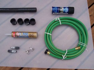
Materials for collector
- 1 – sheet of Coroplast plastic sheet (4’x8’x4mm) cut to 22″x90″ – $8.50
- 1 – 4′ of 1 1/4″ ABS tubing – $6 (Note: Do not use PVC as it softens at too low a temperature causing leaks.)
- 4 – 1 1/4″ ABS caps – $10
- 2 – threaded 1/2″ hose nipples – $1.00
- 1 – cartridge of silicone adhesive/sealant suitable for plastic – $3.50(Note: since original publication I’ve found Marine GOOP to be better)
- 1 – can of flat black spray paint – $5.00
Materials for frame
- 1 – 1/2″ sheet of plywood (4’x8′) cut to 24″x8′ – $8.00
- 1 – 3/4″ sheet of polystyrene (2’x8′) cut to 22″x87.5″ – $2.50
- 2 – 2×3 x 8′ – $8.00 used
- 1 – at least 4’x10′ of transparent plastic sheet – $0 scrap
- misc screws and staples
Materials for tank / water circulation
- 1 – cooler (or other water tank, preferably insulated) – $20 but I already had one scrap
- 1 – 15ft of 5/8″ garden hose – $5.50
- 2 – 1/2″ hose clamps – $1.50
Total cost of materials = $59.50
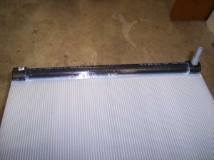
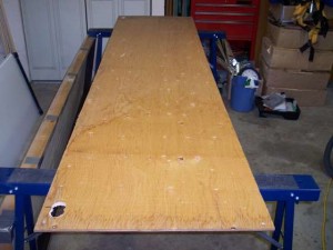
Build the collector
- Use an exacto knife to cut the corrugated plastic sheet to 22″x90″. When cutting lengthwise, be sure to cut in a single channel for the whole length.
- Cut the ABS pipe into two lengths, each 20.25″ long. Check that when a cap is placed on either end, the total length is 22″. I picked this width so it would fit between the roof rafters in my attic.
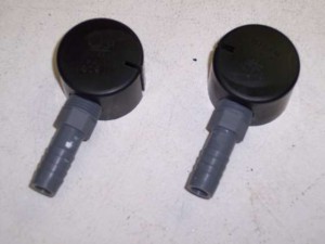
- Drill a 3/4″ hole in the side of two of the ABS caps. This will be easier if you pre-drill with a smaller bit and gradually increase the size.
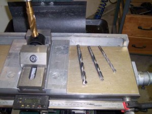
- Enlarge the holes with a coarse round file until you can just thread in the nipples. I did not have a tap of the right thread, so I planned to just glue the nipples in place.
- Drill a 3/4 diameter semicircular notch in the end of each ABS tube. This is easiest if you clamp them end to end in a vise. Alternatively you could drill this hole in the ABS tube before cutting it, and then just cut through the center of the hole to make the notches. These notches fit around the nipple end when the ABS caps are in place.
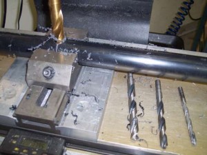
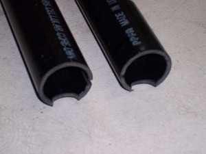
- Using a table saw with a fence, carefully rip a slot down the full length of each ABS tube. The resulting cross section should look like a “C”. The ABS tube tends to compress as you cut, so that when you are done, the slot will not be as wide as the width of your saw blade. Feed each tube through the saw a second time to clean up the cut for a consistent width.
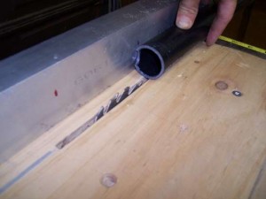
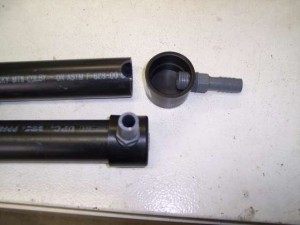
- Repeat the slot cutting process with the ABS caps, keeping in mind what direction you want the nipples to be pointing when the panel is fully assembled.
- Do a dry fit, assembling the ABS tubes, caps, and hose nipples. You may need to carve a bit out of the notch to get the slot in the tube to line up with the slot in the cap.
- Repeat the dry fit on the end of the corrugated plastic sheet. Carve up the ABS as needed to get a nice fit everywhere.
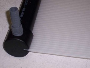
- After everything fits nicely, repeat the assembly, applying adhesive to all mating surfaces before assembly, and applying a bead of adhesive to all seams after assembly.
- Repeat for the other end of the corrugated plastic.
- Allow to dry for at least 24 hours.
- After drying, cut the garden hose in half and clamp the cut ends to the nipples.
- Fill the panel with water (just connect the garden hose to a tap on your house) and check for leaks.
- If there are any leaks, drain the panel, dry the area around the leak thoroughly and seal with more adhesive, allowing another 24 hours to dry.
- If you are interested in calculating the efficiency of your collector later, you need to know its volume. This is a good time to drain it into a bucket and measure the volume (including the hoses). Mine contained 7.2 litres.
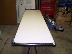
- Once all leaks have been sealed, paint the surface of the collector black.
Build the frame
You could use the collector as is. Just lay it out in the sun and pump water through it. However, much more heat can be captured by building an insulated enclosure for it.
- Cut one 2×3 to two lengths of 22″ for the ends of the frame. Screw the other 2 2x3s into the ends to make a rectangular frame.
- Wrap the transparent plastic around this frame to make a transparent lid to fit over the collector. In my case this is for test purposes only, since I intend to eventually install the collector between roof rafters underneath transparent roofing material which will provide a ready made frame.
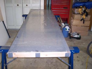
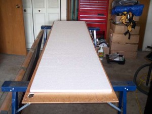
- Cut the plywood to 24″x8′.
- Cut the styrofoam sheet to 7’4″ by 3’9″ and place it centered on the plywood. This will be the insulation for the back of the panel.
- Test fit the collector and drill 3/4″ holes in the plywood where the hoses will stick through. Make one of these holes into a slot by drilling two 3/4″ holes side by side and cutting away the wood between them. This is to allow for thermal expansion of the collector. Plastics typically have a high coefficient of thermal expansion. If you restrict the panel from expanding, it may warp and cause a leak.
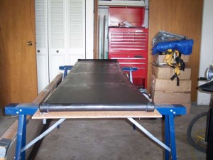
- Now stack the whole works together: First the plywood, then polystyrene, then the collector, then the transparent cover.
- Secure the transparent cover to the plywood back with several clamps (or you can screw it on, but initially you might want to be able to remove it easily for access to the collector).
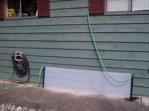
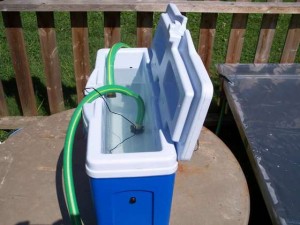
Fill the panel
Filling the panel in such a way that you get all the air bubbles out is easier said than done unless you use a few simple tricks.
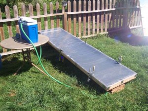
- Lift one end of the panel and rest it on a chair or other object (I used my fence). Rest the other end on a couple blocks of wood so that the bottom hose will have clearance from the ground (remember I eventually want to install this on the underside of a roof, between rafters, which is why I made the hoses connect through the back instead of the sides).
- Mount your storage tank higher than the panel and stick the top hose in it.
- Connect the bottom hose to a tap on your house and turn on the water gently.
- Watch as the panel fills. When water starts coming out of the top hose, let it continue and fill the tank.
- As the tank is filling, temporarily tilt the panel so the corner where the top nipple exits is the highest point. This forces any air in the system to move towards the exit nipple where it will be expelled.
- Once you stop seeing air coming out of the top hose, return the panel to its previous position.
- Turn off the tap. Introduce a kink in the bottom hose to keep the water from flowing out. Then remove the hose from the tap.
- Keep the bottom hose kinked, and the top hose under water in the tank. Raise the end of the bottom hose above the water level in the tank and release the kink. Slowly lower the end of the hose until water starts coming out, then plug it with your thumb and quickly stick the end under water in the tank creating a sealed system with as little air in it as possible.
- Orient the hoses so that the bottom hose draws water from the bottom of the tank and the top hose delivers water to the top of the tank. Whatever you do, be careful to always keep both hose ends under water or you will “break the seal” and introduce air into the system which will prevent circulation by thermo-siphoning.
Testing
If you have removed all the air and have a sealed system and there is enough sunlight hitting the panel, it should start thermo-siphoning almost instantly.
- Turn the panel towards the sun and raise or lower the top end of the panel to better aim it towards the sun. One end of the panel must be raised higher than the other in order for thermo-siphoning to work. The storage tank must also be kept higher than the top end of the panel.
- Feel the top hose where it exits the panel. It should be hot if your setup is thermo-siphoning. The bottom hose should still be cool. If this isn’t the case, it probably means you have a vapor lock (air bubbles) somewhere preventing the water from circulating. Connect the bottom hose to your tap again and repeat the filling process, attempting to remove all the air bubbles.
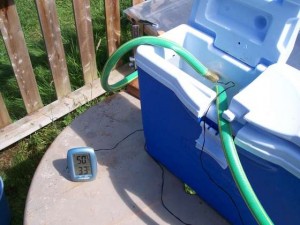
- Once thermo-siphoning starts, use a digital thermometer with probe to measure the water temperature. By sticking the temperature probe inside the ends of the hoses, you can measure the inlet and exit temperatures of the collector. It took me about a minute after filling before I had my thermometer set up. At that time the inlet temperature was 23 degrees C (basically the initial temperature of the water) and the exit temperature was 50.7 degrees C (123 degrees F).
- Measure the inlet temperature over a period of an hour or so (or till the temperature stabilizes). The inlet temperature should always be the lowest temperature in the system. Measuring here will give conservative results when calculating the amount of energy transfered to the water.
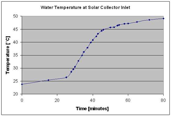
Results
See the image below for a plot of temperature vs time.
Thermo-Siphon Flow Rate
The hoses are setup such that the bottom hose draws cold water from the bottom of the tank and the top hose delivers hot water to the top of the tank. The water in the tank does not mix much due to the low flow rate. Therefore the water drawn into the bottom hose stays at almost a constant temperature (the original water temperature) until all the water in the tank has been drawn out and been replaced by warm water that has passed through the collector. Dividing the tank volume by the time till the temperature starts to rise gives a rough approximation of the flow rate through the collector.
Tank volume = 12.8 litres (Note: I filled it this much so the total water volume would be 20 litres)
Time to empty: 25 minutes
Calculated thermo-siphon flow rate: 0.8 litres per minute
Time to empty: 25 minutes
Calculated thermo-siphon flow rate: 0.8 litres per minute
Note that the thermo-siphon flow rate decreases as all the water heats up and the density imbalance difference between the tank and the panel is less.
Power Calculation
The temperature change I was able to achieve was about 23°C over a period of 1 hour. The heat capacity of water is 4.18 kJ/kg/°C. There were 20kg of water in the system. Given this information it is possible to calculate the average power that was actually input into the water:
Power = 4.18 kJ/kg/degreesC * 20 kg * 23 degreesC / 3600 seconds = 0.53 kW or 530 Watts.
Efficiency Calculation
The collector area is about 1.4 m2. Energy available from sunlight is about 1000 W/m2. Therefore the panel receives about 1400 W of incoming power when aimed directly towards the sun. The efficiency is simply the power actually extracted divided by the power available.
Efficiency = 530 Watts / 1400 Watts = 0.378 or 38%.
This is quite comparable to commercially available solar collectors. However, I’m doing this in my back yard with uninsulated hoses, a non-air tight panel, a single plastic pane that’s slightly opaque, an open topped tank and no pump. The fact that I can achieve commercial level efficiencies with this setup is a testament to the design and indicates there is plenty of room for improvement in the industry.
Why this panel design works so well
Most home brew and commercial solar collector designs I have seen use metal (usually copper) tubing to carry the water through the panel. Metal fins are attached to the copper tubing. The fins are painted black. The fins heat up and conduct the heat to the tubing. Metal is a good conductor, but the heat has to travel a long way through a thin cross-section to reach the tubing. In my design, I used plastic which is a poor conductor, but the heat only has to travel about 0.3mm through a very large cross-section from the front surface of the panel to the water. I’ll illustrate why this is better.
There is a property of any thermal system called thermal conductance that indicates how much heat (power) can be transfered from point ‘a’ to point ‘b’ for a given temperature differential. The formula is:
Thermal Conductance = K * A / L
where:
K = thermal conductivity (a physical property of the material)
A = cross-sectional area through which heat must travel
L = distance heat must travel (the distance from ‘a’ to ‘b’).
where:
K = thermal conductivity (a physical property of the material)
A = cross-sectional area through which heat must travel
L = distance heat must travel (the distance from ‘a’ to ‘b’).
Compari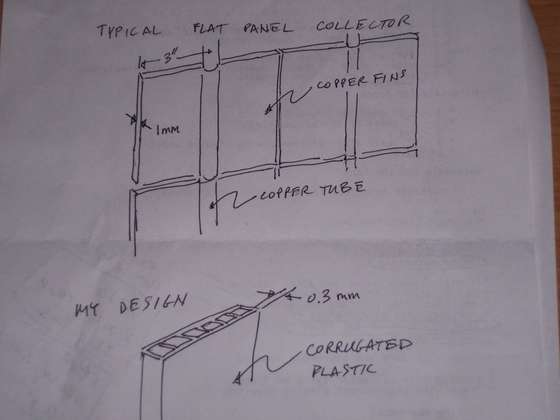 son of a typcial tube-and-fin collector to a corrugated plastic collector.
son of a typcial tube-and-fin collector to a corrugated plastic collector.
Lets calculate the thermal conductance of a typical flat panel collector.
Assume the panel is 2’x8′ with 4 copper tubes running lengthwise and fins sticking out 3″ on either side of every tube (6″ per tube x 4 tubes fills our 2′ width). Suppose the fins are 1mm thick and also made of copper. When the fins heat up, the cross sectional area through which this heat must be conducted to reach the tubes is 1mm * 8 ft * 8 fins = 19504 mm2. The average distance the heat must be conducted is 1/2 the fin width or 1.5″ = 38 mm. The conductivity of copper is about 0.4 W/mm/degreeC.
Therefore the thermal conductance from the collector surface to the water is 0.4 W/mm/degreeC * 19504 mm2 / 38 mm = 205W/degreeC. In other words, a 1 degreeC temperature difference between the water and the fin will result in 205W of heat transfer. But the panel is receiving something on the order of 1400 W of incoming power from sunlight. To transfer all that power to the water by conduction alone the fins would have to heat up to 7 degrees C higher than the water temperature.
This is assuming a 1mm thick copper fin which is better than you’re likely to find in most DIY tube and fin designs. For example, some DIY books I have read recommend making fins from aluminum cans (typical wall thickness under 0.15mm).
Now repeat the calculation for the corrugated plastic panel.
The cross sectional area through which heat must be conducted is the receiving area of the panel itself (2′ * 8′ = 1486448 mm2). The distance the heat must travel to reach the water is just the thickness of the plastic wall or about 0.3mm. The conductivity of plastic is about 0.0001 W/mm/degreeC. Note that it is over 1000 times lower than copper which makes sense since plastic is general thought of as an insulator, not a conductor.
Therefore the thermal conductance of the system is 0.0001 W/mm/degreeC * 1486448 mm2 / 0.3 mm = 495 W/degreeC. In other words, a 1 degreeC temperature difference between the water and the collector surface will result in 495 W of heat transfer into the water. To transfer 1400W, the panel surface only needs to heat up about 3 degreesC hotter than the water.
Of course in practice, not all of that 1400W goes into the water. The conductance from the collector surface to the water is in parallel with another conductance from the collector surface to the outside air. The relative values of those two conductances determines how much heat goes where (Aside: this is analogous to current in an electrical circuit with two resistors in parallel.
Conclusion
In spite of the much lower thermal conductivity of plastic, using a corrugated plastic sheet as a collector achieves over twice the conductance between the collector surface and the water when compared to a copper tube-and-fin design with 1mm thick fins.
Image 1

Engineer Ram Babu
S.I.T.M.
0 comments:
Post a Comment
Thanks